| |
Rogers CuClad 250 2-Layer 10mil Immersion Gold PCB – High Frequency Microwave Applications
1. Introduction to Rogers CuClad 250 PCB
Rogers CuClad 250 laminates are cross plied, woven fiberglass and PTFE composite laminates that offer low dielectric constants ranging from 2.40 to 2.55 at 10GHz. CuClad 250 laminates use a higher fiberglass/PTFE ratio to provide mechanical properties approaching those of conventional substrates. These laminates provide better dimensional stability and lower thermal expansion in all directions.
CuClad 250 laminates feature cross-plied construction (alternating layers of coated fiberglass plies oriented 90° to each other) which provides true electrical and mechanical isotropy in the XY plane. This 2-layer rigid PCB is constructed entirely with CuClad 250 as the core material, making it ideal for radars, microwave components (LNAs, filters, couplers), and electronic countermeasure systems.
2. Key Features of Rogers CuClad 250 PCB
Dielectric Constant: 2.40 to 2.55 at 10 GHz / 1MHz Dissipation Factor: 0.0017 at 10 GHz Low Moisture Absorption: 0.03% Strong Peel Strength: 14 lbs/in Low outgassing: TML 0.01%, CVCM 0.0%, WVR 0.0% Cross Plied Woven Fiberglass construction High PTFE to Glass Ratio Balanced electrical and mechanical properties Better Dk uniformity than non-woven fiberglass reinforced laminates Low circuit losses at high frequency
3. Benefits of Rogers CuClad 250 PCB
Cross-plied construction provides balanced electrical and mechanical properties Low Dk supports wider line widths for lower insertion loss Low circuit losses at high frequency Better dielectric constant uniformity than comparable non-woven fiberglass reinforced laminates Well suited for Er sensitive circuits Excellent dimensional stability and lower thermal expansion in all directions True electrical and mechanical isotropy in the XY plane
4. PCB Construction Details
| Item | Specification |
|---|
| Base material | Rogers CuClad 250 (PTFE/woven fiberglass composite) |
| Layer count | 2-layer rigid |
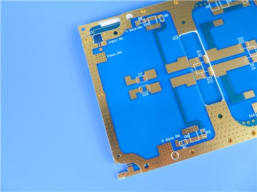
| Board dimensions | 48.6mm x 76.9mm = 1 PCS, ±0.15mm |
| Minimum Trace/Space | 4/6 mils |
| Minimum Hole Size | 0.3mm |
| Blind vias | No |
| Finished board thickness | 0.4mm (10mil core) |
| Finished Cu weight | 1 oz (35 μm / 1.4 mils) outer layers |
| Via plating thickness | 20 μm |
| Surface finish | Immersion Gold |
| Top Silkscreen | White |
| Bottom Silkscreen | No |
| Top Solder Mask | Blue |
| Bottom Solder Mask | No |
| 100% Electrical test | Used prior to shipment |
5. PCB Stackup (2-Layer Rigid Structure)
Copper_layer_1 (Top) – 35 μm (1 oz)
Rogers CuClad 250 Core – 0.254 mm (10mil)
Copper_layer_2 (Bottom) – 35 μm (1 oz)
Total thickness: 0.4mm (including copper layers)
6. PCB Statistics
Components: 12
Total Pads: 34
Thru Hole Pads: 18
Top SMT Pads: 16
Bottom SMT Pads: 0
Vias: 9
Nets: 2
7. Rogers CuClad 250 Material – Product Introduction
CuClad® series laminates are woven fiberglass/PTFE composite materials for use as printed circuit board substrates. Using precision control of the fiberglass/PTFE ratio, CuClad laminates offer a range of choices from the lowest dielectric constant and loss tangent to a more highly reinforced laminate with better dimensional stability.
The woven fiberglass reinforcement in CuClad products provides greater dimensional stability than non-woven fiber glass reinforced PTFE based laminates of similar dielectric constants. The consistency and control of the PTFE coated fiberglass cloth allows Rogers to offer a greater variety of dielectric constants and produces a laminate with better dielectric constant uniformity than comparable non-woven fiberglass reinforced laminates. These properties make CuClad an attractive choice for filters, couplers and low noise amplifiers.
CuClad laminates are crossplied (alternating layers of coated fiberglass plies are oriented 90° to each other). This provides true electrical and mechanical isotropy in the XY plane, a feature unique to CuClad laminates. No other woven or nonwoven fiberglass reinforced PTFE based laminates make this claim.
 CuClad 250.jpg)
8. Features and Benefits Summary
| Feature | Benefit |
|---|
| Dk 2.40-2.55 @ 10 GHz | Low dielectric constant supports wider line widths for lower insertion loss |
| Df 0.0017 @ 10 GHz | Ultra-low loss for high-frequency microwave designs |
| Cross-plied woven fiberglass | True electrical and mechanical isotropy in XY plane |
| Peel strength 14 lbs/in | Excellent copper adhesion for reliable assemblies |
| Low moisture absorption 0.03% | Minimal impact on electrical properties in humid environments |
| Low outgassing (TML 0.01%, CVCM 0.0%) | Suitable for space and vacuum applications |
| High PTFE/glass ratio | Balanced mechanical properties approaching conventional substrates |
9. CuClad 250 Typical Properties (Data Sheet)
| Property | Typical Value | Condition | Test Method |
|---|
| Dielectric Constant @ 10 GHz | 2.40 to 2.55 | C23/50 | IPC-TM-650 2.5.5.5 |
| Dielectric Constant @ 1MHz | 2.40 to 2.60 | C23/50 | IPC-TM-650 2.5.5.3 |
| Dissipation Factor @ 10 GHz | 0.0017 | C23/50 | IPC-TM-650 2.5.5.5 |
| Thermal Coefficient of Er (ppm/°C) | -153 | -10°C to +140°C | IPC-TM-650 2.5.5.5 Adapted |
| Peel Strength (lbs/in) | 14 | After Thermal Stress | IPC-TM-650 2.4.8 |
| Volume Resistivity (MΩ-cm) | 8.0 x 10⁹ | C96/35/90 | IPC-TM-650 2.5.17.1 |
| Surface Resistivity (MΩ) | 1.5 x 10⁸ | C96/35/90 | IPC-TM-650 2.5.17.1 |
| Arc Resistance (seconds) | >180 | D48/50 | ASTM D-495 |
| Tensile Modulus (kpsi) | 725, 572 | A, 23°C | ASTM D-638 |
| Tensile Strength (kpsi) | 26.0, 20.5 | A, 23°C | ASTM D-882 |
| Compressive Modulus (kpsi) | 342 | A, 23°C | ASTM D-695 |
| Flexural Modulus (kpsi) | 456 | A, 23°C | ASTM D-790 |
| Dielectric Breakdown (kv) | >45 | D48/50 | ASTM D-149 |
| Specific Gravity (g/cm³) | 2.31 | A, 23°C | ASTM D-792 Method A |
| Water Absorption (%) | 0.03 | E1/105 + D24/23 | MIL-S-13949H / IPC-TM-650 2.6.2.2 |
| CTE X/Y/Z (ppm/°C) | 18 / 19 / 177 | 0°C to 100°C | IPC-TM-650 2.4.24 |
| Thermal Conductivity | 0.25 | 100°C | ASTM E-1225 |
| Outgassing - TML / CVCM / WVR (%) | 0.01 / 0.00 / 0.00 | 125°C, ≤10⁻⁶ torr | NASA SP-R-0022A |
| Flammability | Meets UL94-V0 | C48/23/50, E24/125 | UL 94 / IPC-TM-650 2.3.10 |
10. Primary Application Areas
Radars, Electronic Countermeasures, Electronic Support Measures Microwave Components (LNAs, filters, couplers, etc.) Phased array antennas Low noise amplifiers Satellite communication systems
11. Quality Assurance
Type of artwork supplied: Gerber RS-274-X Accepted standard: IPC-Class-2 Availability: Worldwide 100% Electrical test prior to shipment
12. Standard Thicknesses, Panel Sizes & Claddings
| Parameter | Options |
|---|
| Standard Thicknesses | 0.005" (0.13mm), 0.010" (0.25mm), 0.020" (0.51mm), 0.030" (0.76mm), 0.060" (1.52mm), 0.125" (3.18mm) ± tolerance |
| Standard Panel Sizes | 36" x 36" (914 x 914mm) in crossplied configuration; additional sizes available |
| Standard Claddings | EDC: ½ oz (18μm), 1 oz (35μm), 2 oz (70μm); rolled copper and heavy metal ground plane available |
|
|